RouterBoard x2, EdgeRouter x2 でネットワークを組み、BGPを使ったルート交換をしてみました。
題して「Router4台使って、擬似インターネットを構築してみました。」です。
前回の記事時点から、ルータの数が倍になったので、少々面白くなりました。
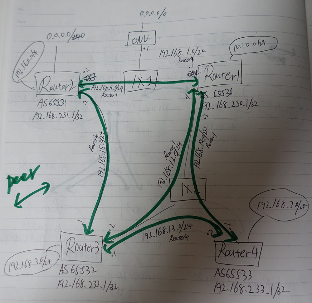
今回のネットワーク構成
今回は、Router4台を使い、IXっぽいものということでL2SWも用意して、実際にインターネット上にありそうなモノにしました。
Router1, Router2 に関しては、Transit ASということで、広告のフィルタは無し。(RouterBoard使用)
Router3, Router4 は、非Transit ASです。フィルタで自ASが持っているネットワークのみ広告する。(EdgeRouter使用)
設定
設定が多いので、対象の部分だけに絞って載せます。
(珍しくWebfigの内容ではなく、コマンドです)
Router1 (RouterBoard)
RouterBoardにはloopbackインターフェースというのが無いみたい。なので、bridgeインターフェースをloopbackインターフェースのように使ってます。(重要ポイント)
/interface bridge
add fast-forward=no name=bridge-main
add name=loopback
/interface gre6
add ipsec-secret=xxxxxxxxxxxxxxx!keepalive local-address=yyyyyyyyy::1 name=gre-toForce remote-address=zzzzzzzzzzz::1
/interface vlan
add interface=ether5 name=vlan_router3 vlan-id=100
add interface=ether5 name=vlan_router4 vlan-id=101
/ip address
add address=10.1.0.1/24 interface=bridge-main network=10.1.0.0
add address=192.168.1.254/24 interface=bridge-wan network=192.168.1.0
add address=192.168.11.1/24 interface=gre-toForce network=192.168.11.0
add address=192.168.0.1/24 interface=ether5 network=192.168.0.0
add address=192.168.12.1/24 interface=vlan_router3 network=192.168.12.0
add address=192.168.14.2/24 interface=vlan_router4 network=192.168.14.0
add address=192.168.230.1 interface=loopback network=192.168.230.1
/ip route
add distance=1 gateway=192.168.1.1
add distance=2 gateway=gre-toForce
add distance=1 dst-address=192.168.231.1/32 gateway=192.168.11.2
add distance=1 dst-address=192.168.232.1/32 gateway=192.168.12.2
add distance=1 dst-address=192.168.233.1/32 gateway=192.168.14.1
/routing bgp instance
set default router-id=192.168.230.1
/routing bgp network
add network=10.1.0.0/24 synchronize=no
add network=192.168.1.0/24 synchronize=no
add network=192.168.14.0/24 synchronize=no
add network=192.168.12.0/24 synchronize=no
add network=192.168.11.0/24 synchronize=no
add network=192.168.230.0/24 synchronize=no
/routing bgp peer
add multihop=yes name=peer1 remote-address=192.168.231.1 remote-as=65531 ttl=2 update-source=192.168.230.1
add multihop=yes name=peer4 remote-address=192.168.233.1 remote-as=65533 ttl=2 update-source=192.168.230.1
add multihop=yes name=peer3 remote-address=192.168.232.1 remote-as=65532 ttl=2 update-source=192.168.230.1
Router2 (RouterBoard)
Router1と同様の方法でloopbackインターフェースを用意
/interface bridge
add name=bridge-local
add name=loopback
/interface gre6
add ipsec-secret=xxxxxxxx !keepalive local-address=zzzzzzzzzzzz::1 name=gre-toPlatinum remote-address=yyyyyyyyyyyy::1
/ip address
add address=172.16.0.1/24 interface=bridge-local network=172.16.0.0
add address=192.168.1.253/24 disabled=yes interface=ether1-gateway network=192.168.1.0
add address=192.168.11.2/24 interface=gre-toPlatinum network=192.168.11.0
add address=192.168.231.1 interface=loopback network=192.168.231.1
add address=192.168.15.2/24 interface=ether2 network=192.168.15.0
/ip route
add distance=1 dst-address=192.168.230.1/32 gateway=192.168.11.1
add distance=1 dst-address=192.168.232.1/32 gateway=192.168.15.1
/routing bgp instance
set default as=65531 router-id=192.168.231.1
/routing bgp network
add network=172.16.0.0/24 synchronize=no
add network=192.168.15.0/24 synchronize=no
add network=192.168.231.0/24 synchronize=no
/routing bgp peer
add multihop=yes name=peer1 remote-address=192.168.230.1 remote-as=65530 ttl=2 update-source=192.168.231.1
add multihop=yes name=peer3 remote-address=192.168.232.1 remote-as=65532 ttl=2 update-source=192.168.231.1
Router3 (EdgeRouter)
interfaces {
    ethernet eth0 {
        duplex auto
        speed auto
        vif 100 {
            address 192.168.12.2/24
            description vlan_router1
            mtu 1500
        }
        vif 102 {
            address 192.168.13.1/24
            description vlan_router4
            mtu 1500
        }
    }
    ethernet eth1 {
        address 192.168.15.1/24
        duplex auto
        speed auto
    }
    loopback lo {
        address 192.168.232.1/32
    }
    switch switch0 {
        address 192.168.3.1/24
        mtu 1500
        switch-port {
            interface eth2 {
            }
            interface eth3 {
            }
            interface eth4 {
            }
            vlan-aware disable
        }
    }
}
policy {
    prefix-list EXPORT-AS65532 {
        rule 10 {
            action permit
            prefix 192.168.3.0/24
        }
        rule 20 {
            action permit
            prefix 192.168.232.1/32
        }
    }
}
protocols {
    bgp 65532 {
        neighbor 192.168.230.1 {
            ebgp-multihop 2
            prefix-list {
                export EXPORT-AS65532
            }
            remote-as 65530
            update-source 192.168.232.1
        }
        neighbor 192.168.231.1 {
            ebgp-multihop 2
            prefix-list {
                export EXPORT-AS65532
            }
            remote-as 65531
            update-source 192.168.232.1
        }
        neighbor 192.168.233.1 {
            ebgp-multihop 2
            prefix-list {
                export EXPORT-AS65532
            }
            remote-as 65533
            update-source 192.168.232.1
        }
        network 192.168.3.0/24 {
        }
        network 192.168.232.1/32 {
        }
        parameters {
            router-id 192.168.232.1
        }
    }
    static {
        route 0.0.0.0/0 {
            next-hop 192.168.230.1 {
                distance 100
            }
        }
        route 192.168.230.1/32 {
            next-hop 192.168.12.1 {
            }
        }
        route 192.168.231.1/32 {
            next-hop 192.168.15.2 {
            }
        }
        route 192.168.233.1/32 {
            next-hop 192.168.13.2 {
            }
        }
    }
}
Router4 (EdgeRouter)
interfaces {
    ethernet eth0 {
        duplex auto
        speed auto
        vif 101 {
            address 192.168.14.1/24
            description vlan_router1
            mtu 1500
        }
        vif 102 {
            address 192.168.13.2/24
            description vlan_router3
        }
    }
    loopback lo {
        address 192.168.233.1/32
    }
    switch switch0 {
        address 192.168.2.1/24
        mtu 1500
        switch-port {
            interface eth2 {
            }
            interface eth3 {
            }
            vlan-aware disable
        }
    }
}
policy {
    prefix-list EXPORT-65533 {
        rule 10 {
            action permit
            prefix 192.168.2.0/24
        }
        rule 20 {
            action permit
            prefix 192.168.233.1/32
        }
        rule 30 {
            action permit
            prefix 192.168.13.0/24
        }
    }
}
protocols {
    bgp 65533 {
        neighbor 192.168.230.1 {
            ebgp-multihop 2
            prefix-list {
                export EXPORT-65533
            }
            remote-as 65530
            update-source 192.168.233.1
        }
        neighbor 192.168.232.1 {
            ebgp-multihop 2
            prefix-list {
                export EXPORT-65533
            }
            remote-as 65532
            update-source 192.168.233.1
        }
        network 192.168.2.0/24 {
        }
        network 192.168.13.0/24 {
        }
        network 192.168.233.0/24 {
        }
        network 192.168.233.1/32 {
        }
        parameters {
            router-id 192.168.233.1
        }
    }
    static {
        route 0.0.0.0/0 {
            next-hop 192.168.230.1 {
                distance 100
            }
        }
        route 192.168.230.1/32 {
            next-hop 192.168.14.2 {
            }
        }
        route 192.168.232.1/32 {
            next-hop 192.168.13.1 {
            }
        }
    }
}
動作確認
Router1 (RouterBoard) のrouting table
Router3, Router4 を経由してのRouter2という経路がないことを確認。
[admin@platinum] > ip route print
Flags: X - disabled, A - active, D - dynamic, C - connect, S - static, r - rip, b - bgp, o - ospf, m - mme, B - blackhole, U - unreachable, P - prohibit
 #      DST-ADDRESS        PREF-SRC        GATEWAY            DISTANCE
 0 A S  0.0.0.0/0                          192.168.1.1               1
 1   S  0.0.0.0/0                          gre-toForce               2
 2 ADC  10.1.0.0/24        10.1.0.1        bridge-main               0
 3 ADb  172.16.0.0/24                      192.168.231.1            20
 4 ADC  192.168.0.0/24     192.168.0.1     ether5                    0
 5 ADC  192.168.1.0/24     192.168.1.254   bridge-wan                0
 6 ADb  192.168.2.0/24                     192.168.233.1            20
 7 ADb  192.168.3.0/24                     192.168.232.1            20
 8  Db  192.168.3.0/24                     192.168.231.1            20
 9 ADC  192.168.11.0/24    192.168.11.1    gre-toForce               0
10 ADC  192.168.12.0/24    192.168.12.1    vlan_router3              0
11 ADb  192.168.13.0/24                    192.168.233.1            20
12 ADC  192.168.14.0/24    192.168.14.2    vlan_router4              0
13 ADb  192.168.15.0/24                    192.168.231.1            20
14 ADC  192.168.230.1/32   192.168.230.1   loopback                  0
15 ADb  192.168.231.0/24                   192.168.231.1            20
16 A S  192.168.231.1/32                   192.168.11.2              1
17 A S  192.168.232.1/32                   192.168.12.2              1
18  Db  192.168.232.1/32                   192.168.232.1            20
19 A S  192.168.233.1/32                   192.168.14.1              1
20  Db  192.168.233.1/32                   192.168.233.1            20
Router2 (RouterBoard) のrouting table
Router3, Router4 を経由してのRouter1が無いことを確認。
[admin@force] > ip route print
Flags: X - disabled, A - active, D - dynamic, C - connect, S - static, r - rip, b - bgp, o - ospf, m - mme, B - blackhole, U - unreachable, P - prohibit
 #      DST-ADDRESS        PREF-SRC        GATEWAY            DISTANCE
 0 ADS  0.0.0.0/0                          biglobe                   0
 2 ADb  10.1.0.0/24                        192.168.230.1            20
 4 ADC  172.16.0.0/24      172.16.0.1      bridge-local              0
 5 ADb  192.168.1.0/24                     192.168.230.1            20
 6 ADb  192.168.2.0/24                     192.168.230.1            20
 7 ADb  192.168.3.0/24                     192.168.232.1            20
 8  Db  192.168.3.0/24                     192.168.230.1            20
 9 ADC  192.168.11.0/24    192.168.11.2    gre-toPlatinum            0
10  Db  192.168.11.0/24                    192.168.230.1            20
11 ADb  192.168.12.0/24                    192.168.230.1            20
12 ADb  192.168.13.0/24                    192.168.230.1            20
13 ADb  192.168.14.0/24                    192.168.230.1            20
14 ADC  192.168.15.0/24    192.168.15.2    ether2                    0
15 ADb  192.168.230.0/24                   192.168.230.1            20
16 A S  192.168.230.1/32                   192.168.11.1              1
17 ADC  192.168.231.1/32   192.168.231.1   loopback                  0
18 A S  192.168.232.1/32                   192.168.15.1              1
19  Db  192.168.232.1/32                   192.168.232.1            20
Router3 (EdgeRouter) のrouting table
Router1, Router2両方から経路が来ていること。そして、Router4経由が無いこと。
ubnt@route3:~$ show ip bgp cidr-only
BGP table version is 70, local router ID is 192.168.232.1
Status codes: s suppressed, d damped, h history, * valid, > best, i - internal, l - labeled
              S Stale
Origin codes: i - IGP, e - EGP, ? - incomplete
    Network          Next Hop            Metric    LocPrf       Weight Path
*>  10.1.0.0/24      192.168.230.1        0                     0       65530 i
*                    192.168.231.1        0                     0       65531 65530 i
*>  172.16.0.0/24    192.168.231.1        0                     0       65531 i
*                    192.168.230.1        0                     0       65530 65531 i
*>  192.168.232.1/32 0.0.0.0                       100          32768    i
*>  192.168.233.1/32 192.168.233.1        0                     0       65533 i

Total number of prefixes 6
Router4 (EdgeRouter) のrouting table
Router3経由が無いこと
ubnt@router4:~$ show ip bgp cidr-only
BGP table version is 21, local router ID is 192.168.233.1
Status codes: s suppressed, d damped, h history, * valid, > best, i - internal, l - labeled
              S Stale
Origin codes: i - IGP, e - EGP, ? - incomplete
    Network          Next Hop            Metric    LocPrf       Weight Path
*>  8.8.8.8/32       192.168.230.1        0                     0       65530 i
*>  10.1.0.0/24      192.168.230.1        0                     0       65530 i
*>  49.212.142.68/32 192.168.230.1        0                     0       65530 i
*>  172.16.0.0/24    192.168.230.1        0                     0       65530 65531 i
*>  192.168.232.1/32 192.168.232.1        0                     0       65532 i
*>  192.168.233.1/32 0.0.0.0                       100          32768    i

Total number of prefixes 6
まとめ
なんか良い感じに互いにルートの広告ができ、想定通りのネットワークが組めました。
だが、各種ステータスを確認するコマンドがいまいちわからない。
OSが違うと扱い方が全然異なるので大変。でも、思想的なのが伝わってくる感じがするので面白い。
BGPの奥深さを知ってしまった。(沼に落ちそう)
フルルート欲しい。